
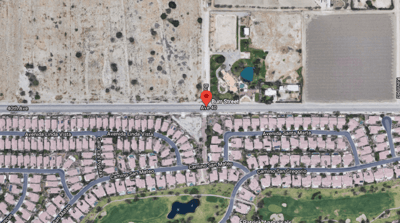
The LS 81-03 service area is expected to grow in a manner similar to the entirety of the WRP 7 service area. Year 2030 ADWF for the lift station are projected to reach 715 gpm with PWWF reaching 2150 gpm. CVWD desired a new lift station that can handle these future flows. In addition to not being able to accommodate future flows, the old lift station was located in the middle of a residential area and had received numerous odor complaints over the years. CVWD purchased an unimproved one-acre parcel of land on the northeast corner of Burr St. and Avenue 43, approximately 300 feet north of the old lift station site, to construct the new lift station and contracted LEE + RO to design the new lift station, in addition to the decommissioning and demolition of the old lift station once the new lift station was built.
CVWD’s sanitation system design and construction standards and regulations are published in their Development Design Manual (DDM). Using DDM criteria for calculating peak flows, maximum pump cycling and specification of required emergency storage and operation volumes mandated utilization of a relatively large and deep wet well.
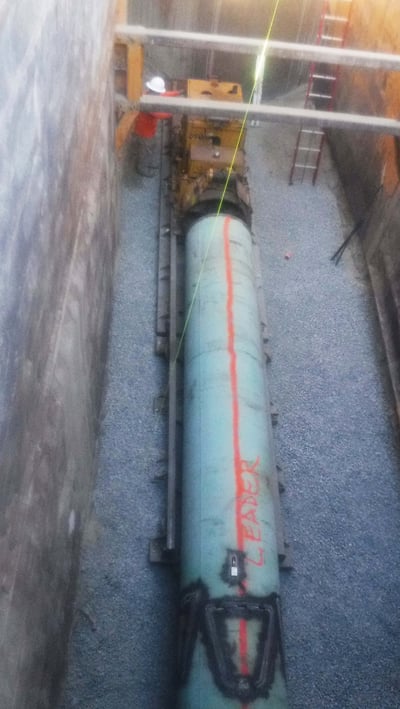
Flows from LS 81-03 are conveyed to WRP-7 via an 18-inch diameter force main. This force main shares flows with downstream lift station LS 81-07. Because each of these two lift stations impact the performance of the other through pressure, the existing pump capacity and flow rates of the downstream LS 81-07 had to be considered when selecting the pumps for the new LS 81-03.
The existing gravity collection sewers feeding the old lift station are deep with inverts ranging from 15 feet to 18 feet below the surface. In addition to the existing collection sewer lines, a series of underground utilities share the street, either paralleling or crossing these sewer lines. Intercepting and rerouting the sewer flow from the old lift station to the new lift station, without disrupting the operation of the existing system, presented unique challenges for the construction of the new collection sewer system. A total of seven (7) sewer lines, collecting sewage from the surrounding service areas, had to be redirected to the new lift station’s location.
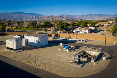
The old lift station was located in the middle of a residential area and had received numerous odor complaints over the years due to high hydrogen sulfide (H2S) gas concentrations in the wastewater. The South Coast Air Quality Management District (SCAQMD) permit to operate for the new lift station reduced the allowable H2S measurements from 1 ppm under the old lift station permit to 0.51 ppm at the new lift station, a 50% reduction.
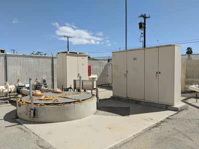
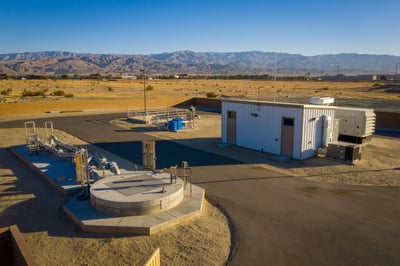
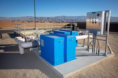
The new replacement lift station consists of a wet well, submersible pumps, valves and piping, instrumentation, with electrical distribution system, PLC and SCADA system housed in a climate-controlled electrical building, diesel-fueled emergency standby generator, and odor control system facilities all located within a graded and paved site, secured by an 8-foot-tall concrete masonry unit (CMU) block perimeter wall with landscaping, irrigation and area lighting.
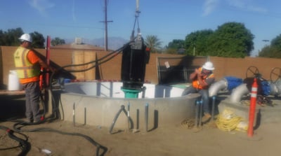
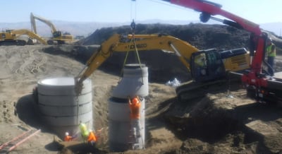
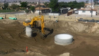
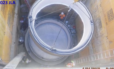
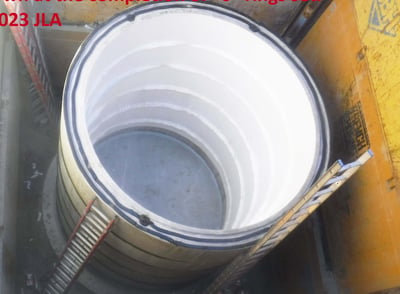
A 12-foot diameter x 48-foot-deep T-Lock lined concrete wet well was designed to provide the necessary emergency storage and operation volumes required by the DDM in addition to accommodating the deep existing gravity flow collection sewers. The T-lock high density polyethylene (HDPE) liner provides structural protection from corrosion due to naturally occurring hydrogen sulfide gas (H2S) in the sewer system.
The hydraulic model was calibrated at both LS 81-03 and LS 81-07 to document peak flows and to confirm the operations at each lift station. LS 81-07 is equipped with two pumps with a design point of 1,500 gpm at 90 feet of total dynamic head (TDH). Fortunately, the model indicated no issues in the shared force main for either lift station.
System curves were developed for the purpose of sizing the pumps. Two system curves were developed, one for current ADWF and one for future PWWF. This was done to provide CVWD with an operational system where both current and future needs are met with one set of pumps. Two submersible chopper pumps (duty/standby) with a design point of 2,400 gpm at 145 feet TDH, each with VFD-driven 200 HP submersible inverter-duty motors were provided. The wet well operates in fill and draw mode during periods of lesser flows with the pump operating at variable speeds to handle the increased flows.
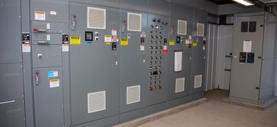
A climate controlled electrical building was designed to protect the new electrical equipment from the desert heat. The air conditioner system was sized to meet both the electrical heat load generated as well as the desert solar heat gain. The electrical building houses the motor control center containing the motor VFDs and soft starters, odor control fan motor starters, automatic transfer switch, various electrical and instrumentation panels, and the SCADA system telemetry cabinet. A new 480V, 1000A electrical service and a 500-kW diesel-fueled emergency standby generator were also provided.
To minimize the number of conflicts, LEE + RO conducted detailed research and investigations to locate and determine the depth of the existing nearby and crossing underground utilities. These utilities were potholed to determine the actual depth and locations for the design plans. The new primary collection sewer line was then aligned to minimize the risk of potential conflicts with adjacent utilities. For the deeper sewer lines, a wider trench width was considered when laying out the alignment to ensure that existing utilities were not exposed unnecessarily.
To simplify the myriad of sewer lines into a primary line, points of confluence were evaluated from the existing gravity collection system to reduce the number of laterals in the primary line. Additionally, strategic points of the existing collection system were intercepted upstream to discharge into the new lift station wet well to reduce the size of the new primary line.
The wet well was designed with a concrete cover with a stainless-steel double-door hatch for access into the wet well. The wet well lid confines the odorous hydrogen sulfide (H2S) gas generated from the raw sewage within the wet well. The lift station foul air treatment facilities designed include a wood chip bio filter bed for primary odor control in addition to a dry media scrubber for use as backup when the wood chip bed is out of service for maintenance or changing out the wood chip media. These odor control facilities are connected to the wet well with PVC foul air piping. A negative pressure is maintained in the wet well to pull the foul air from the wet well and convey it to the odor control equipment for processing. The odor control facilities performance continues to meet the exhaust requirements specified in the SCAQMD’s permit to operate.
 |
 |
At over 40 years old, all of the existing equipment at the old LS 81-03 was past its useful service life, the existing wet well capacity did not meet CVWD’s Development Design Manual requirements, and the lift station could not accommodate year 2030 flows. In addition, the old lift station was located in the middle of a residential area and had received numerous odor complaints over the years. LEE + RO designed a brand-new lift station in a new location and in accordance with CVWD’s DDM requirements with all new equipment that should provide CVWD with a minimum of another 40 years of service.


_tinified.jpg?width=400&name=Solution%205%20(2)_tinified.jpg)