
The Coachella Valley Water District (CVWD) owns and operates wastewater Lift Station 81-01 (LS 81-01), which is located in the City of Palm Desert, CA. The lift station was equipped with two wet wells. The main wet well was a 10-foot diameter x 26-foot deep concrete wet well and was equipped with two 135 HP submersible pumps, each rated for 2,000 gpm at 185 ft. TDH. The secondary wet well is a 9-foot diameter x 26-foot-deep concrete wet well hydraulically connected to the main wet well via an 18-inch diameter PVC pipe. The secondary wet well is equipped with a Godwin HL250M diesel engine-driven standby emergency pump with a capacity of 3,500 gpm.
LS 81-01 was in dire need of rehabilitation. The main wet well needed concrete repair, the submersible pumps, motors and instrumentation needed to be replaced, and the wet well discharge piping and valves needed replacement. The secondary wet well also required concrete repairs and replacement of the discharge piping and valves. The main electrical switchboard, motor control center (MCC), PLC and telemetry equipment was past its useful service life. In addition, the existing emergency generator also needed to be replaced, as did the odor control system and equipment.
CVWD wanted the lift station to be able to handle flows projected to the year 2045 and the existing wet well was of insufficient size to provide the required storage volume to handle the projected flows. CVWD operations staff reported a lack of capacity at the old primary wet well resulting in increased operating cycles for the submersible pumps. In addition, the lift station had to remain in service while the new civil, mechanical, structural, electrical, and instrumentation & controls improvements were constructed. Temporary odor control facilities were required while the existing wood chip bed was demolished and the new one constructed. The existing collection system sewers had to be intercepted and rerouted to the new wet well and tie-in connections made to the existing force mains.
Determining a location for a new, larger wet well in addition to all new electrical, instrumentation & controls equipment, odor control facilities, and rerouting of the collection system sewers proved to be challenging due to the tightly constrained site. Complicating the assignment, we needed to maintain the existing lift station operational while also providing maintenance access for the site during construction.
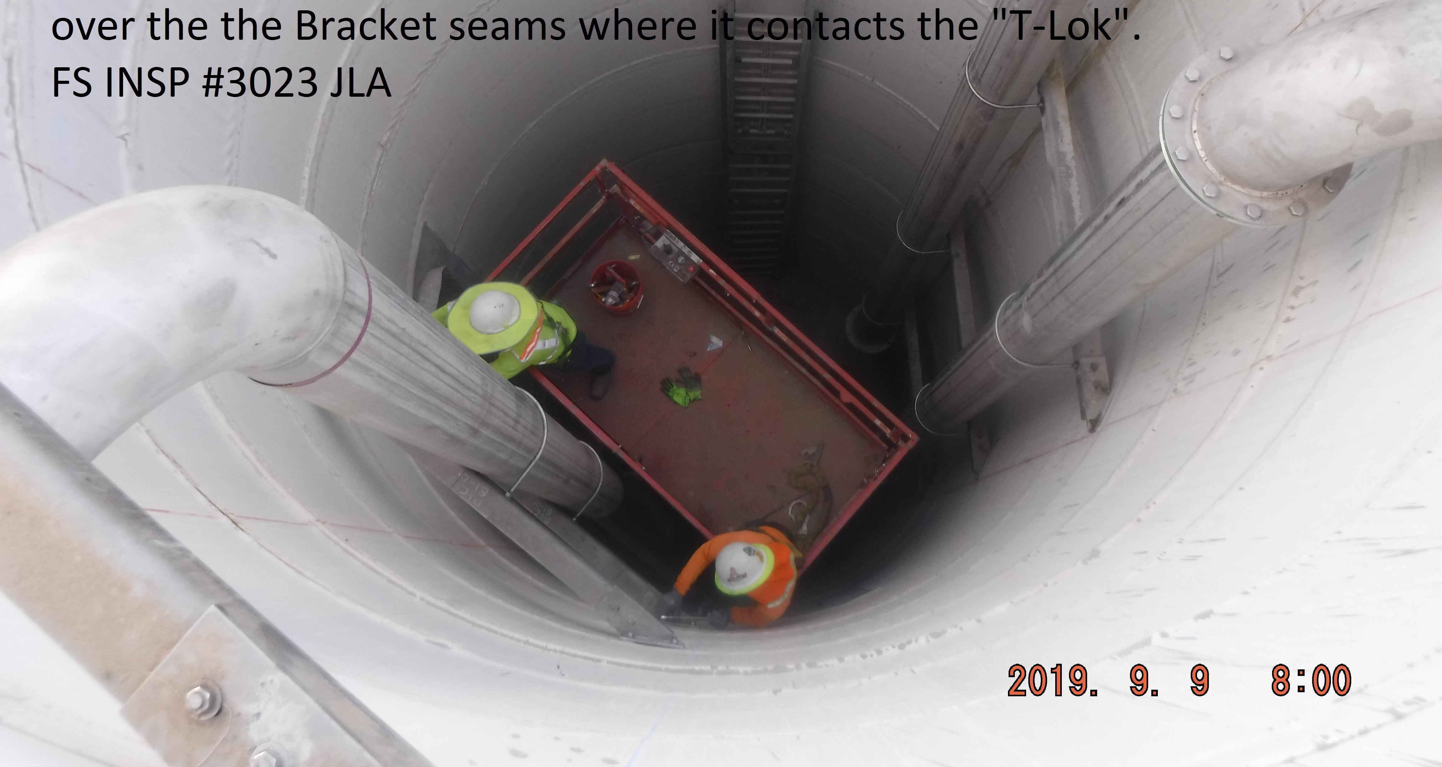
Using CVWD’s Development Design Manual (DDM) criteria, peak wet weather flows (PWWF) for year 2045 were calculated to be 3,692 gpm. The existing wet well dimensions of 10-foot diameter x 26-foot deep did not meet the DDM requirements for emergency storage and operating capacity. A new 12-foot diameter x 43-foot-deep precast concrete wet well with a T-Lock liner was designed to provide the necessary storage and operating volume specified by DDM criteria, providing a maximum of no more than six (6) pump cycles per hour. The new wet well was located such that the existing primary wet well and pumps could remain in service while the new wet well could be constructed.
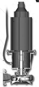
Although the new wet well was sized to ultimately accommodate larger submersible pumps, the expected service life of a submersible chopper pump would not meet the 25 years of service required for reaching year 2045 flows. LEE + RO designed the new pumps for a 15-year service life and year 2034 peak flow of 3,340 gpm. Two (2) 8-inch 3,340 gpm chopper pumps with VFD-driven 125 HP inverter duty submersible motors were specified. Because of the lower minimum flows experienced over the first several years, these smaller pumps maintain better efficiency due to their lower operating range.
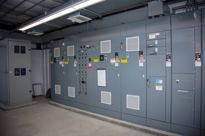
Year 2045 flows of 3,692 gpm will require larger pumps and motors. LEE + RO not only designed the wet well large enough to accommodate these flows, the lift station electrical distribution and control system was also sized and configured to be able to accommodate the larger future pump motors. The new main switchboard, motor control centers, automatic transfer switch, and 400 kW diesel-fueled emergency standby generator were all designed to accommodate increased future loading requirements. Because the lift station is located in the desert, a new climate-controlled electrical building was designed to house the new electrical gear.
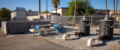
The lift station had to remain in service and the odor control facilities also had to remain operational during construction. As there was insufficient available space to construct a new wood chip bed prior to demolishing the existing wood chip bed, LEE + RO designed a foul air treatment system for use as temporary odor control facilities that allowed the demolition of the existing wood chip bed. The temporary odor control facilities, consisting of two dry media scrubbers, were also incorporated into the final odor control system for use as a backup for the wood chip bed.